Arduino Uno and Nano
Connection
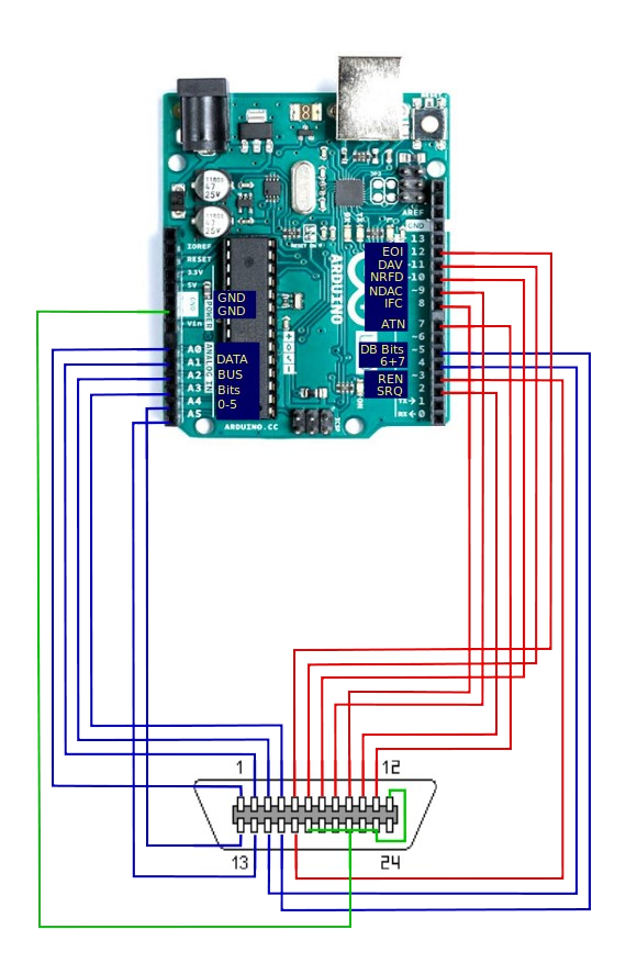
These connections are required between the Arduino UNO/Nano and the IEEE488 connector:
| Arduino | GPIB connector | Function |
|---|---|---|
| A0 | 1 | DIO1 |
| A1 | 2 | DIO2 |
| A2 | 3 | DIO3 |
| A3 | 4 | DIO4 |
| D12 | 5 | EOI |
| D11 | 6 | DAV |
| D10 | 7 | NRFD |
| D9 | 8 | NDAC |
| D8 | 9 | IFC |
| D2 | 10 | SRQ |
| D7 | 11 | ATN |
| GND | 12 | Shield |
| A4 | 13 | DIO5 |
| A5 | 14 | DIO6 |
| D4 | 15 | DIO7 |
| D5 | 16 | DIO8 |
| D3 | 17 | REN |
| GND | 18,19,20,21,22,23 | GND |
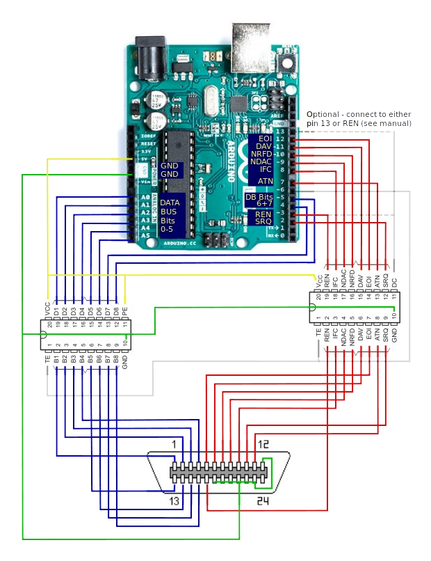
Wiring diagram
When using SN75160 and SN75161 integrated circuits, the connections involve at least one
extra pin to control the talk-enable (TE) pin of the IC. The PE pin on the
SN75160 is connected to VCC to maintain a 3-state outputs when TE is high.
Connecting PE to ground will allow the outputs to function in pullup-enable mode
when TE is high.
On the SN75161, the DC pin can be connected to a separate GPIO pin on the Uno/Nano,
or, since ren is always asserted when in controller mode and de-asserted in device mode,
to the GPIO pin used for the REN signal.