Arduino Mega 2560
Connection
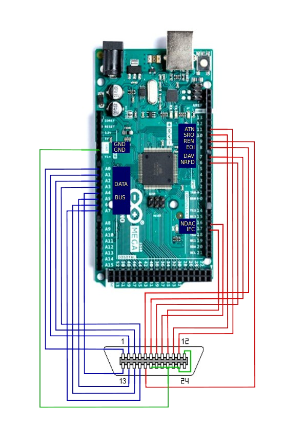
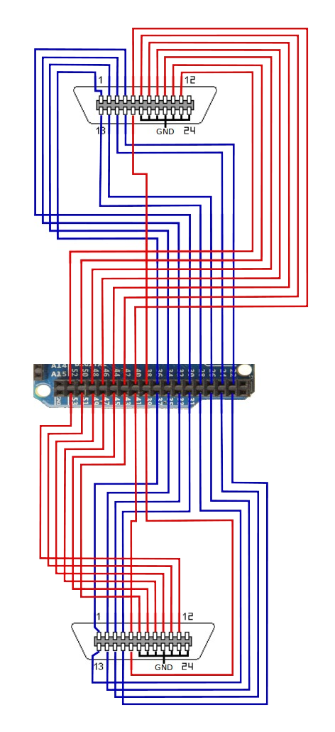
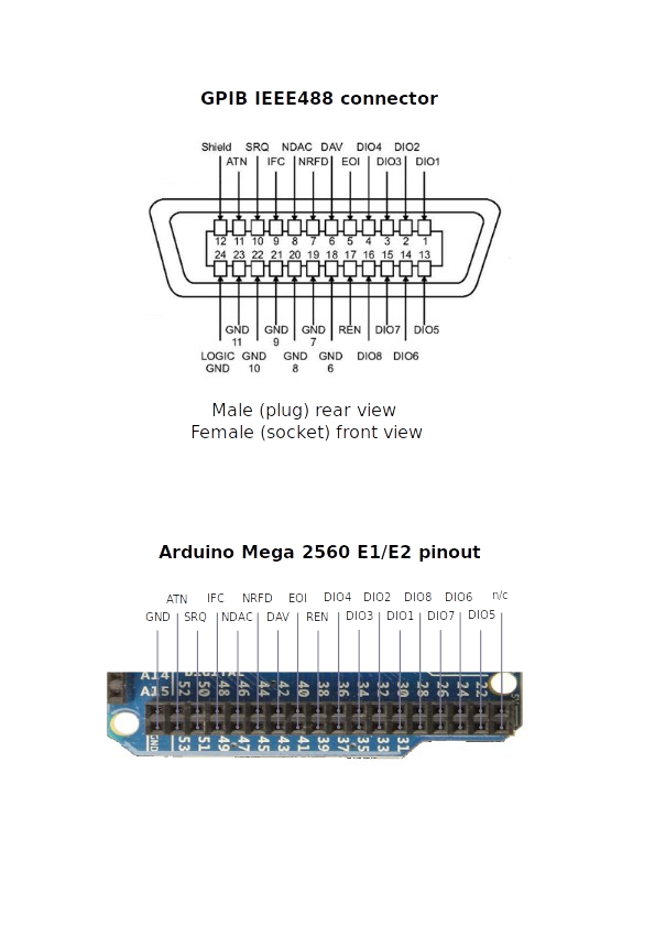
These connections are required between the Arduino Mega 2560 and the IEEE488 connector. There are 3 different wiring diagrams, a Default one, E1 and E2:
| Arduino | GPIB connector | Function | ||
| D | E1 | E2 | ||
| A0 | 30 | 37 | 1 | DIO1 |
| A1 | 32 | 35 | 2 | DIO2 |
| A2 | 34 | 33 | 3 | DIO3 |
| A3 | 36 | 31 | 4 | DIO4 |
| D8 | 40 | 41 | 5 | EOI |
| D7 | 42 | 43 | 6 | DAV |
| D6 | 44 | 45 | 7 | NRFD |
| D16 | 46 | 47 | 8 | NDAC |
| D17 | 48 | 49 | 9 | IFC |
| D10 | 50 | 51 | 10 | SRQ |
| D11 | 52 | 53 | 11 | ATN |
| GND | GND | GND | 12 | Shield |
| A4 | 22 | 29 | 13 | DIO5 |
| A5 | 24 | 27 | 14 | DIO6 |
| A6 | 26 | 25 | 15 | DIO7 |
| A7 | 28 | 23 | 16 | DIO8 |
| D9 | 38 | 39 | 17 | REN |
| GND | GND | GND | 18,19,20,21,22,23 | GND |
The default layout on the Mega was chosen so as to leave pins A8-A15 and the two
rows of pins at the top of the board free for expansion including for displays and other
peripherals.
Pins 16 and 17 correspond to Serial2. As these have been used for controlling
signals on the GPIB bus, they cannot be used for serial communication. If
Serial2.begin is added to the sketch, these pins will be enabled for serial
communication and will no longer function as GPIB control signals. In addition to the
default serial port (RX0 and TX0), Serial1 and Serial3 are still
available for expansion if required. These two pins were chosen for GPIB signals as they
belong to port H along with pins 6 – 9.
Wiring diagram - default layout